#Risa 3d floor data entry toolbar software#
RISA offers one of the most popular structural engineering software suites in the United States for multi-material structural analysis. Type in "S" or "segment" in the member information.Skip to content or navigation. If this happens, run the model with PDelta turned off and check for huge deflections or instabilities, indicating improper modeling. If you have properly specified the PDelta, maybe you run the model and you get an error message saying "PDelta diverging".

If you leave this blank and try to solve your model using AISC 14th, it will not perform calculations on your members.
#Risa 3d floor data entry toolbar code#
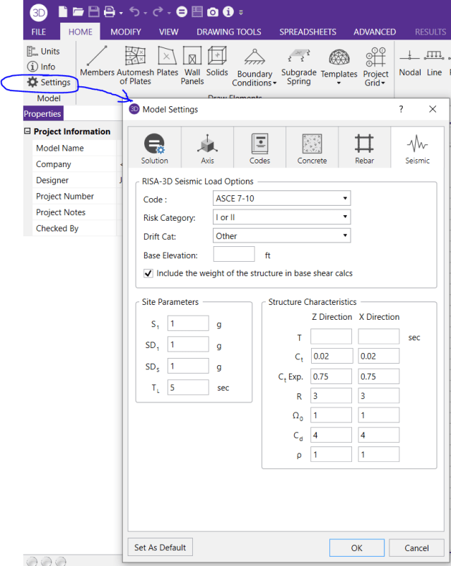
Well, the first step is to check your code selection. If this happens with your model, the model may be unstable under the given loads, or there may be local instabilities present. If this error is displayed, the P-Delta displacements have reached a level where they are more than 1, times greater than the maximum original displacements. If the P-Delta process is diverging dramatically, it will be stopped before numerical problems develop and an error will be displayed. For a 3D model, this P-Delta calculation is done for the member's local y and local z directions. These shear forces are applied at the member ends. This type of analysis is called "P-Delta" because the magnitude of the secondary moment is equal to "P", the axial force in the member, times "Delta", the distance one end of the member is offset from the other end.

These secondary effects, for members not platescan be accurately approximated through the use of P-Delta analysis. The deflections in the members of the model may induce secondary moments due to the fact that the ends of the member may no longer be co-linear in the deflected position. The results now indicate zero moment at the base, which is what you want for this pinned base situation. View the reactions directly on the screen by selecting "Show the Reactions" on the Model Display Options tab.

Now, check that the reactions solved by RISA are what you are expecting. In reality though, for a column with a pinned base, we can hold the Y rotation by setting the drop-down box to "reaction" as we do not expect to see this rotation in the field. If pins are chosen for all support points, there are 6 joint aspects for the model to solve and it becomes unstable. For a structural frame system, modifying the boundary condition supports can resolve the instabilities. If you are unable to find the source of the instability it may be because of a setting in the program.

Right away, error messages! This means there is the potential for an unlimited displacement. RISA Tips and Tricks for Structural Engineers You've assigned your loads, then applied your loads, and then created your load combinations. You've assigned the boundary supports, checked the code solutions, and double checked that the Y axis is vertical. You've spent hours carefully inputting your structure, all the individual nodes, members, pinned or fixed connection types, getting the orientation of each member correct, checking the unbraced lengths, the k values. It can also be a source of much frustration if you lose sight of your precise data entry. Structural engineering design software can be an invaluable resource to perform efficient, engineered solutions of both simple and complex-framed structures.


 0 kommentar(er)
